A contact arc in a circuit breaker is an extremely complex electro-thermo-hydro-dynamic process and that we never fully mathematically describe the detailed physics of an arc. Our goal, here, is to develop an approximate arc model such that we can treat an arc as a circuit element, and analyze electric circuits containing arcs.
During normal circuit breaker operation, the arc when present, is in a continual state of change. It is dynamically lengthened by parting contacts and by electromagnetic forces which push it away from its original trajectory. It is dynamically heated by its current. It is dynamically cooled by its environment and, perhaps, by other auxiliary means (forced gas flow, cool containment walls, etc.). And, dependent on the net rate of energy absorption (heating minus cooling), it dynamically grows in cross-sectional area.
As the arc changes physically and thermally, it also changes electrically. A change in the electrical characteristics of the arc, in turn, changes the amount of through current that the external electrical circuit can supply. Therefore, an engineering description (which is all that we seek) of a circuit breaker arc must include a dynamic description of the breaker-electrical network interaction. Now, we will discuss the components of an electrical arc: Cathodes, Anodes and Plasma Columns.
The two arc electrodes are referred to as the cathode and the anode. Electrons are injected into the arc by the cathode at a rate proportional to the arc current. Arc electrons are collected by the anode at the same rate since the current must be continuous. The region between the cathode and the anode is divided into three sub-regions: the cathode fall region, the plasma column (sometimes referred to as the positive column), and the anode fall region.
A typical voltage profile along the path of a “short” arc is shown in Figure 5.7.
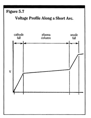
By short, we mean that the voltage drop across the plasma column is small in comparison to the combined voltage drops across the cathode and anode fall regions. Typically, this will occur when the physical length of the plasma column is small. The cathode and anode fall regions are the transition regions between the metallic cathode and anode electrodes and the gaseous plasma column. The magnitudes of the electric fields within the cathode and the anode fall regions are much higher than the magnitudes of the fields within the metallic cathode and anode. And, much higher than the magnitude of the field within the plasma region. Higher electric fields are, by definition, higher voltage drops per unit distance, and thus the use of the term “fall,” as in “voltage fall” in the descriptions of the cathode and anode transition regions.
The voltage drops or “falls” within the cathode and anode fall regions are strong functions of the materials used as cathode and anode electrodes, but relatively weak functions of the current level within the arc. The energy required to completely remove an electron from the surface of a material body is defined as the “work function” of that material. Expressed as an equivalent voltage (energy divided by the charge of one electron), the vacuum work functions of most metallic elements are approximately 4 to 5 volts. The detailed physics of electron emission and collection in cathode and anode regions under arc conditions is of such complexity that only a limited number of low current, simplified cases have been theoretically analyzed by researchers. For our purposes, it is sufficient to say that the cathode and anode voltage drops are “of the order” of the cathode and anode work functions.
The actual surface area of the cathode electron emission and anode electron collection varies with the total arc current. The current densities within these active areas, however, are extremely large, particularly so for the cathode. Current densities exceeding 106 A/cm2, and surface temperatures exceeding 4000oK have been postulated by Lee for cathode “spots”. At these current densities and temperature electron emission is a combination of thermionic and field emission. Electrons with enough thermal energy can thermionically escape the surface of the cathode but, due to the large concentration of positive ions in front of the cathode, a high surface electric field is also present. It enables surface electrons to tunnel through a reduced surface work function energy barrier and be accelerated away or “emitted” by field emission.
Even higher surface “spot” temperatures can be present at the anode. When electrons leave the cathode, they take energy with them. Therefore, the cathode is actually cooled by their exit (On a net basis, however, the cathode is heated by the I2R heating within the cathode spot and the energy of incoming positive ions). When electrons arrive at the anode, they dump their energy into the anode surface and heat it up (in addition to the anode I2R heating).
Dependent on the actual surface spot temperatures, anode and cathode evaporated surface material will transfer from hotter to cooler surfaces if the gap is sufficiently small (as in a breaker at initial contact parting). Some investigators have shown that material transfer can be a function of peak arc current, where the peak surface temperature transfers from cathode to anode as the peak arc current increases beyond a certain threshold.
The plasma column in an arc is composed of a partially ionized gas. Gas molecules are “ionized” when neutral gas molecules separate into negatively charged free electrons and positively charged ions. This occurs by a number of different processes: high electric field electron and positive-ion collisions; absorption of radiation; and thermal ionization, ionization by means of collisions with high temperature (i.e. high energy) electrons, positive ions and neutral molecules. All of these processes occur in an arc; the relative importance of each is dependent on location within the plasma column and the strength of the arc. The energy input to the plasma column is the Joule heating due to mobile current carriers.
Since there is a large difference between the mass of an electron and the mass of a positive ion, there is a large difference between the response of an electron and a positive ion to an applied electric field. By far, the majority of the current within the plasma column of an arc is carried by electrons. Therefore, the initial energy transfer to the plasma is to the electron gas within the plasma. But very rapidly, by means of collisions, this energy is shared with the plasma positive ions and the background neutral molecules. Thus, in time intervals of interest to the circuit breaker design engineer, and to a very good degree of approximation, the plasma is in a state of thermal equilibrium. That is, all components (electrons, ions, and neutral molecules) within a spatial region are at the same temperature.
At thermal equilibrium conditions, the rate of ionization within a particular differential region is balanced by an equal rate of ion-electron recombination. Also, the net concentrations or densities of electrons and positive ions are approximately equal and monotonically dependent on the plasma temperature.
The conductivity of the plasma region in the arc is a strong function of the plasma temperature. The higher the temperature, the higher the level of thermal ionization and carrier concentration. The more carriers, the less the value of electric field needed to support a given level of current density (i.e. the conductivity increases). This positive feedback effect – more current → higher heating → more carriers → more current for a given level of external excitation – partially accounts for the steady-state negative differential resistance of an arc.
Another contributor to the steady-state negative differential resistance of an arc is the cross-sectional spreading of the plasma column at higher current levels. As the temperature of the active (ionized) plasma column increases, so too does the temperature of the gas surrounding the plasma column due to thermal conduction (and perhaps convection and radiation). At high enough temperatures above a threshold temperature, the immediate surrounding gas will also undergo thermal ionization. There will then be additional carriers present to carry the arc current, increasing further the net arc conductivity.
A typical static or steady-state voltage current characteristic of an arc is given in Figure 5.8.
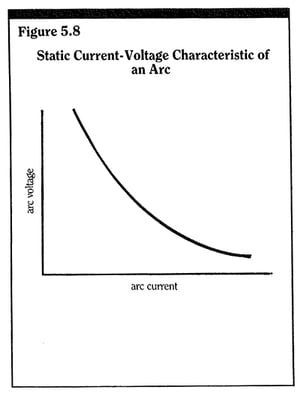
In general, for a given level of arc current, the arc voltage is proportional to the arc length. But for a given arc length, higher arc currents result in lower arc voltage drops due to the static negative differential resistance characteristic.
A common arc control scheme used in many circuit breaker designs, (i.e. a method used to increase the total arc voltage across the main contacts), is to force the arc into an arc baffle or splitter structure. A typical arc baffle structure in a small circuit breaker is shown in Figure 5.9.
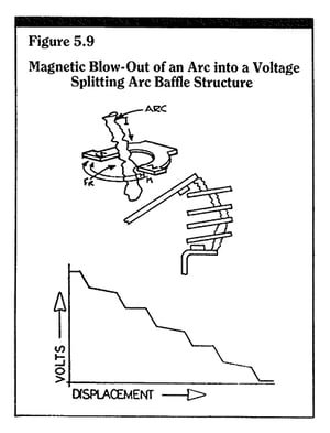
Arc baffles act to break a single arc into several shorter arcs connected in series. The anode and cathode voltage drops of these multiple arcs then add and comprise a major portion of the total device – arc voltage. The movement of the arc into the baffle is initiated by the magnetic Lorentz force, or J x B force, due to the arc current itself (J is the arc current density and B is the magnetic flux density due to the current). This magnetic Lorentz force is the same force which tends to repel the contact faces apart due to constriction current flow paths to minute contact points. The movement of the arc, due to this self-magnetic force, is referred to as magnetic blow-out of the arc.
Magnetic blow-out is also used to force arc movement onto arc “runners”, which are attached to the contact structures (see Figure 5.10).
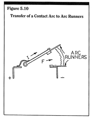
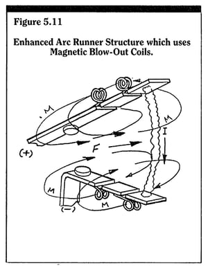
Use of arc runners preserves the more expensive silver alloy contact material by moving the cathode/anode “feet” of the arc off the contacts, and onto the less expensive runner material. In addition, the arc runners present a longer arc path for the arc to traverse and can act as the transfer medium between the inter-contact region and any arc baffle or arc chamber region. Arc runners can be enhanced with the addition of staged electromagnetic drive coils to even further strengthen the magnetic blow-out force along the runner length. (see Figure 5.11).
In circuit breaker design and analysis, the static characteristics of the arc are certainly of interest, but, it is the dynamic characteristics of the arc that are of prime concern. The arc carries the circuit current until an interruption will be successful, that is, whether or not the arc will reignite as the voltage across the breaker contacts rises, is a question that can only be answered by a study of the arc dynamic behavior.


