Large amounts of AC electrical power are always transported by way of balanced three-phase electrical networks. This is for purely economic reasons. Polyphase electrical machines run smoother, and are more efficient, than their single-phase counterparts. And, for a given level of conductor voltage insulation, three-phase transmission circuits utilize a given amount of metallic conductor material better than single-phase lines. Industrial electric power is delivered as three-phase power; while household power is delivered to an area as three-phase power, but then split up and delivered to individual customers as single-phase power.
There are many different types of potential overcurrent faults or disturbances that can occur in three-phase networks. The most common are:
· Balanced three-phase overloads
· An overload in one phase of a three-phase load
· A phase-to-ground fault
· A phase-to-phase fault
· A phase-to-phase-to-ground fault
· A balanced three-phase fault
· Faulty synchronization
In general, each of these overcurrent situations can be electrically simplified. This simplification is a matter of circuit reduction and identification of equivalent sources and impedances.
The steady-state voltages and currents in the phases of a balanced symmetrical three-phase circuit are all equal in magnitude and displaced in phase from each other by 120o. The phase rotation is arbitrarily referenced to one of the phases of the network. The voltages and currents of the other two phases are then said to follow the reference phase, one by 120o and the other by 240o. This particular phase rotation or sequence is denoted as the positive sequence. A balanced three-phase circuit – one with balanced, 120odisplaced, equal-magnitude three-phase sources and balanced three-phase loads – contains only positive sequence voltages and currents.
Since the voltages and currents in one phase of a completely balanced three-phase circuit are identical to the corresponding voltages and currents in the other two phases, except for a phase shift, we can solve the entire balanced network on a per phase basis. That is, we need solve only for the voltages and current in an equivalent single-phase network – the positive sequence network. This equivalent positive sequence single-phase network accounts for the mutual inductive, capacitive and resistive coupling between the actual physical phases of the actual network, by use of equivalent positive sequence inductive, capacitive and resistive elements.
For example – if the three phases of the actual network are labeled (a), (b) and (c), and an inductive element has self-inductance, L, and mutual inductance, M – for the voltage drop across this element in the (a) phase, we have 
But, in a balanced network, we must have 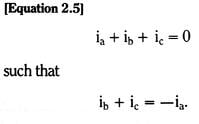
For the inductive voltage drop in the (a) phase, we then have ![]()
We term the equivalent inductance, L-M, the positive sequence self-inductance. Similar developments follow for capacitive and resistive coupling.
A solution for the (a) phase voltages (voltages to neutral) and currents in the resultant equivalent single-phase network (the positive sequence network) is then, in effect, a solution for the entire balanced three-phase network. It is important to note that this technique is only applicable to completely balanced circuits, ones for which Equation 2.5, and a similar one for voltage, are true.
If there is an imbalance in the network, such as a fault in one of the phases, then the circuit voltages and currents will also no longer be balanced. They will no longer be composed of just positive sequence components.
The easiest way to analyze the situation of a normally balanced three-phase circuit with a localized unbalanced section is to separate the total circuit into a balanced portion, usually almost the entire circuit, and an unbalanced portion, usually just the fault current path. This method is commonly called the method of Symmetrical components. The balanced portion is represented by three single-phase sequence networks. The voltages and currents in the sequence networks are the normal mode voltages and currents of the balanced portion of the entire three-phase network.
The normal mode voltages and currents of an electrical network are those voltages and currents which match the normal, or natural, response of the network. A balanced three-phase network has three normal modes; while a balanced two-phase network has only two normal modes. A balanced six-phase network has six normal modes, and so on. Normal modes of a network are distinctive in that they can be excited, and sustained, independent of one another.
We have already discussed one normal mode of symmetrical three-phase network, the positive sequence. A second normal mode for a balanced three-phase network can be excited, if we simply reverse the phase order of the system drive voltages. That is, instead of phases (a), (b) and (c), having the t=0 phase order, 0o, -120o and -240o, we interchange the phasing of (b) and (c) so that the t=0 phase order for (a), (b) and (c) is 0o, -240o and -120o. This phase rotation, which appears in time as (a), (c), (b), is called the negative sequence phase rotation. It is the same phase rotation that would occur if we mechanically drove all the generators in the three-phase network backwards, instead of their normal direction.
The positive and negative sequence phase rotations are shown in vector form in a complex plane in Figure 2.10.
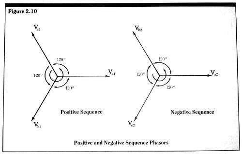
These vectors represent a snapshot of sequence voltages or currents at any one particular time. The actual or real values of the sequence voltages or currents are the projections of the lengths of these vectors onto the horizontal real axis. As time advances, these sets of sequence vectors rotate in a counter-clockwise direction in the complex plane at an angular frequency of 2πf. This rotation can be seen quite clearly by studying the properties of the individual sequence vectors in the complex plane, which, for a sequence voltage, are of the form 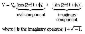
The magnitude of this complex vector at all times is Vm, but, at any one particular time, V has different real and imaginary parts. These real and imaginary parts are the components of the dimensional vector in the complex plane. As time advances, the entire vector rotates in the counter-clockwise direction – that is, the arguments of the trigonometric functions advance – with angular frequency, 2πf. The snapshot of the complex vectors at any one particular time is called a phasor diagram. And the individual vectors in the diagram are termed phasors. Note that each set of sequence phasors contains three equal magnitude (balanced) phasors. The sequence components in each phase are always equal in magnitude. Their only difference is their relative phasing.
The third normal mode for a balanced three-phase electrical network is one which is excited by having all drive generators, in all three phases, in phase. This mode, or sequence, is called the zero sequence. Zero sequence currents in phases (a), (b) and (c) are equal in magnitude (balanced) and in phase. By Kirchoff’s current law, the total zero sequence current (three times the value in any one phase) must then return by some other path than the phase (a), (b) and (c) conductors. For zero sequence currents to exist, there must be a fourth conductor (neutral or ground) return path. Therefore, zero sequence currents cannot flow in a pure “delta system,” one with only three wires.
Zero sequence currents are often called unbalanced currents. In the sense that they are the leftover currents after the positive and negative sequence balanced currents have been accounted for, the statement is true. But it should be recognized that zero sequence currents are also balanced in the sense that equal amounts (one third of the total) of zero sequence current flow in each phase of a three-phase system. A phasor diagram for zero sequence phasors is given in Figure 2.11. It is particularly simple since all three phasors are the same, equal in magnitude and in phase. 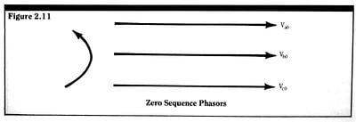
The actual phase voltage or current can now be formed from its sequence or symmetrical components. For example, since we have arbitrarily chosen phase (a) as the reference phase, the components of the (a) phase voltage add up algebraically. That is,
![]()
where Va0, Va1, and Va2 are the zero, positive and negative sequence components of Va, respectively. Phase voltages, Vb and Vc, are also composed of their respective components
Vb = Vb0 + Vb1 + Vb2
and
Vc = Vc0 + Vc1 + Vc2
However, we must treat these additions as vector additions since the components, Vb1, Vb2, Vc1, and Vc2, have both real and imaginary parts.
The standard method of symmetrical components uses the (a) phase symmetrical components as the reference phase sequence components throughout, by defining a pure rotation operator as
A = cos 120o + j sin 120o.
When this operator is multiplied with a complex vector, it rotates the vector 120o in the counter-clockwise direction. Rotation by -120o, which is the same as a +240o rotation, is accomplished by a double +120o rotation- that is, multiplication by a2. Thus we can form 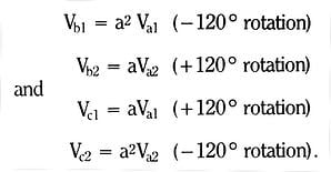
We then have, in matrix form, 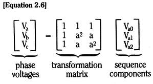
By simple matrix inversion, we can also form 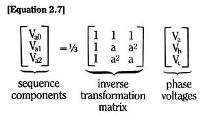
which is the definition of the (a) phase sequence components in terms of the actual phase quantities. A similar set of equations can be developed for the relationships between the phase and the sequence currents.
The positive, negative and zero sequence modes are not the only set of normal modes that can be devised for a symmetrical three-phase electrical network. However, they are the set most commonly used by electrical engineers and, as such, we will not consider any others. In the development given here, our objective is to demonstrate, through the use of symmetrical components that faults in three-phase networks can be simplified and ultimately reduced to single-phase faulted networks.
As stated previously, in an unfaulted, completely balanced three-phase network, only positive sequence voltages and currents are excited. Negative and zero sequence voltages and currents are not excited, and hence do not appear. An unbalanced fault, however, will upset the circuit three-phase symmetry and potentially excite negative and zero sequence voltages and currents. The degree of excitation is dependent on the type and position of the fault and the type of the three-phase circuit. Just as in single-phase networks, we can use Thevenin equivalent networks to represent the sequence network portions of a balanced source network and a balanced load network. And, just as in single-phase networks, we can combine the source and load portions of each sequence network, and arrive at a total Thevenin equivalent network, similar to the single-phase network in Figure 2.4. This total sequence Thevenin equivalent network is shown in Figure 2.12. 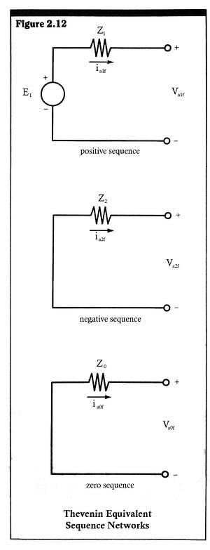
The positive sequence Thevenin network has an equivalent voltage source, E1, and equivalent impedance, Z1. But the Thevenin networks for the negative and zero sequence networks have only internal equivalent impedances, Z2 and X0, respectively. This is due to the fact that the negative and zero sequences have no steady-state excitation.
The terminals of the sequence Thevenin networks are called the fault terminals. The voltages across these terminals are the sequence voltages at the point of the fault in the actual three-phase network. And the sequence currents through these terminals are the sequence currents which flow through the fault path.
Consider now an example of an unbalanced fault. Assume phase (a) is shunted to neutral through a fault resistance, Rf, as shown in Figure 2.13.
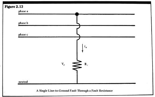
Since (b) and (c) phases are not involved in the fault, we have equations similar to Equation 2.6, thus, 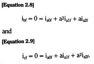
If we subtract these two equations, we obtain
(a2-a) ialf = (a2-a) ia2f
which can be satisfied only if the positive and negative sequence components of the (a) phase current are equal. Substituting this fact back into either Equation 2.8 or Equation 2.9, we see that we must also have
Ia0f = ialf = ia2f
This relationship is satisfied if all the sequence networks of Figure 2.12 are connected in series. Also, at the fault point in the (a) phase, we must have
Vaf = iaf Rf
or
Va0f + Valf + Va2f = (ia0f + ialf + ia2f) Rf = 3 Rf ia0f.
Thus, the external load on the series connection of the three sequence networks is seen to be an equivalent fault resistance of value 3Rf.
The total sequence network connection is shown in Figure 2.14a.
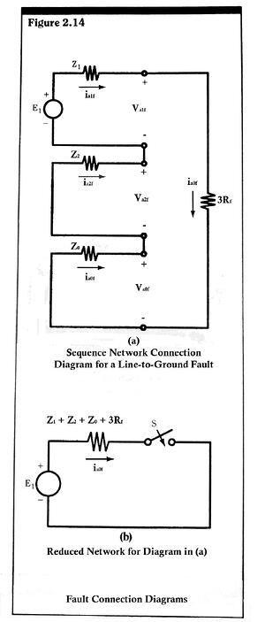
We can simplify the circuit of Figure 2.14a by combining all the impedances in series, to form one total impedance Z,
Z= Z1 + Z2 + Z0 + 3Rf
And by redrawing, to obtain the equivalent form shown in Figure 2.14b. We have added a switch to illustrate that the fault is initiated at a particular time, t.
Although this final form of the fault circuit is now in exactly the same form as the single-phase circuit of Figure 2.4, and can be solved in exactly the same manner as the single-phase circuit, the resulting solution is not the end product we seek. The transient or steady-state current, solved for in the circuits of Figure 2.14a and Figure 2.14b, is the zero sequence component of the fault current. The total (a) phase fault current is given by
Iaf = 3ia0f
This total fault current is then distributed throughout the (a) phase network in both the source and load portions of the total network. Of course, this division of the total fault current among the source and load network occurs in single-phase circuits as well.
All types of faults in three-phase networks can be solved in a manner similar to that of the previous example. The fault boundary conditions are expressed in terms of the sequence components, and the sequence Thevenin networks are connected to satisfy these boundary conditions. The actual phase currents are then formed from the sequence currents, using an equation similar to Equation 2.6.

