---
title: Blog | Mechanical Products | Temperature Rise
description: Temperature Rise | Information on over-current and protection terminology, standards, and circuit breakers
---
[](https://www.mechprod.com/)
Call:**630.953.4100** | Email: [helpme@mechprod.com](mailto:helpme@mechprod.com)
Advanced Design - Legendary Performance - Superior Circuit Protection - Worldwide - Count On It
## [Hot Wire Thermal Circuit Breakers](https://www.mechprod.com/blog-old/bid/294569/Hot-Wire-Thermal-Circuit-Breakers)
- [Tweet](https://twitter.com/share)
In a hot wire circuit breaker a wire of length x0 at reference temperature T0 will expand by length Δx=x0atΔT for temperature rise ΔT. This temperature rise, as in a fuse element, can be generated by the I2R loss in the wire itself.
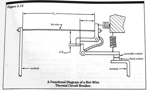
If a given wire extension Δxtrip trips a latch mechanism, which releases a contact separation mechanism (see Figure 3.13), the needed temperature rise within the wire at the detection threshold is then 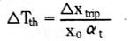
We now have a situation exactly analogous to that of the detection mechanism in a fuse. The exception is that we need only raise the element temperature to the value given by (3.8), not to the melting point. The thermal circuit analysis Equations 3.1 through 3.4, with suitable notation changes, also apply to the hot wire thermal circuit
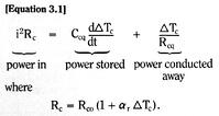
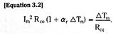
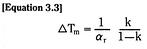
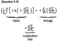
We define
Ar = the wire temperature coefficient of resistivity,
Ro = the wire resistance at the reference temperature,
Rt = the thermal resistance of the wire to the surroundings,
Ith = the steady-state DC current which will raise the temperature by ΔTth (i.e. the long trip time current),
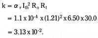
k = the wire resistance temperature sensitivity factor = arIth2RoRt and Ct = the wire thermal capacity.
Thus, just as in Equation 3.4 for a fuse, we have for the hot wire temperature rise ΔT, and for any current I (t) 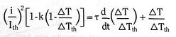
where is the wire thermal time constant
As an example, consider the use of an 80% Nickel – 20% Chromium alloy wire, which has the trade name Nichrome V. This alloy has the average properties:
Reference resistivity: ϱo = 108 x 10-6 Ω-cm (20o)
Coefficient of resistivity: αr = 1.1 x 10⁻⁴/0C (20-500o C)
Coefficient of expansion: αt = 1.7 x 10⁻⁵/oC (10-1000oC)
Specific heat: Cp = 435 J/kgoC.
Assume that the relative extension of the wire at the trip threshold Δxtrip/xo is to be 0.5%. Thus, by (3.8)
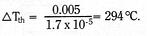
If we choose #30 wire (American wire gauge) we have the following data from the manufacturer:
Wire diameter: 0.010 in
Resistance at reference temp: Ro = 6.500 Ω/ft(20oC)
Mass: 2.86 x 10⁻⁴ lbm/ft
Long time heating current for horizontal wire in air: 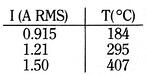
The wire thermal capacity per foot is then
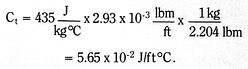
If we use the free air heating-temperature data at I (RMS) = 1.21 A, we have for the wire resistance R
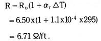
Thus

The free air thermal time constant is then 
The long time threshold current is
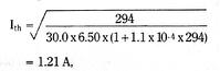
And the wire resistance temperature sensitivity factor k is
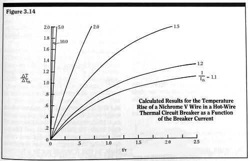
We can now, as we did for the equivalent fuse link, solve for the time it takes for the wire to reach its threshold temperature as a function of current. These solutions are given in Figure 3.14.
Note that for Nichrome V the resistance temperature sensitivity factor is so low that we can, as a fair approximation, neglect the k multiplied term in (3.9) and solve the resulting equation analytically as 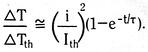
The time to reach the threshold temperature rise td is then given by
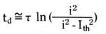
Which, for long (i/Ith)2, reduces to 
0 Comments [Click here to read/write comments](https://www.mechprod.com/blog-old/bid/294569/Hot-Wire-Thermal-Circuit-Breakers#comments-listing)
Tags: [Temperature Rise](https://www.mechprod.com/blog-old/topic/temperature-rise), [Thermal Resistance](https://www.mechprod.com/blog-old/topic/thermal-resistance), [Nichrome V](https://www.mechprod.com/blog-old/topic/nichrome-v)
[All posts](https://www.mechprod.com/blog-old/all)
### Follow us!
### Subscribe by Email
### Latest Posts
### Posts by Month
- [May 2012 (4)](https://www.mechprod.com/blog-old/archive/2012/05)
- [July 2012 (3)](https://www.mechprod.com/blog-old/archive/2012/07)
- [April 2013 (3)](https://www.mechprod.com/blog-old/archive/2013/04)
**Mechanical Products**
**Count on MP for your thermal circuit breaker needs**
Tel: 630.953.4100 | Fax: 630.953.4110 | Email: [helpme@mechprod.com](mailto:helpme@mechprod.com)
**www.mechprod.com**