---
title: Blog | Mechanical Products | Magnetic Torque
description: Magnetic Torque | Information on over-current and protection terminology, standards, and circuit breakers
---
[](https://www.mechprod.com/)
Call:**630.953.4100** | Email: [helpme@mechprod.com](mailto:helpme@mechprod.com)
Advanced Design - Legendary Performance - Superior Circuit Protection - Worldwide - Count On It
## [Magnetic Force](https://www.mechprod.com/blog-old/bid/301839/Magnetic-Force)
- [Tweet](https://twitter.com/share)
It is well known that electromagnets can exert a lifting or attractive force on ferromagnetic materials, such as iron. The force mechanism is the same mechanism by which permanent magnets attract iron objects. Simply stated, near the surfaces of a magnetic material (a ferromagnetic material, one which has a low resistance to the flow of magnetic flux), the density of the energy stored in the magnetic field is much higher on the exterior than on the interior of the material. By the principal of virtual displacement, there will be a mechanical pressure in the direction of the outward normal at the surface of the magnetic material. Since there will be more magnetic field flux at the surfaces of the material that are closest to a nearby magnet, or electro-magnet, the total net force on the magnetic material body will be an attractive force, towards the magnet or electromagnet.
Consider the electromagnet structure shown in figure 4.1 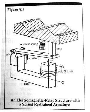
In it a coil of N turns of wire is wrapped around one leg of a ferromagnetic core structure. A movable ferromagnetic armature is hinged to another leg of the core structure. At one end position of swing the armature closes the core structure and completes a closed path of ferromagnetic matter through which magnetic flux can flow. The armature is held away from the core closing position by a spring mechanism, creating a classic "relay" structure.
Coil current will induce magnetic flux within the core material, the armature material, and in the gap between the armature and the coil leg of the core. At a sufficient level of coil current the magnetic attractive force on the armature will exceed the retention force of the spring and the armature will move to its core closed position. If, by its movement, the armature can trip a latch mechanism - releasing a spring driven contact opening mechanism - then based on the level of coil current, we have a trip/no trip decision mechanism (i.e. we have a magnetic circuit breaker).
A simplified armature-latch release mechanism is shown in Figure 4.2. 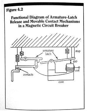
Observe that the armature's path is composed of two sections, a free-movement (spring constraint only) portion, and a latch release (spring constraint and latch restraint force) portion. It is similar to the deflection path of the bi-metallic element in a creep type thermal circuit breaker.
The equation of angular motion of the armature (see Figure 4.3) is given by
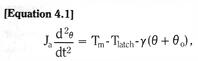
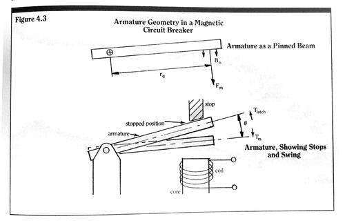
where θ is the armature’s angle, measured from its completely restrained position; θo is an angle measure of the initial pre-load on the restraining spring; γ is the torsional spring constant of the restraining spring; Tlatch is the torque load of the latch release mechanism (Tlatch = 0 during the free movement portion of the armature travel); Tm is the torque due to magnetic attraction, and Ja is the effective angular moment of inertia for the entire armature structure.
In equation 4.1 we have neglected all friction effects due to the armature hinge and air movement. For this structure, the detection time td is defined as the time, measured from the overcurrent inception, required for the armature angle θ to advance to the point of latch release. We will define this latch release angle as θth.
Before discussing the dynamic behavior of the armature, that is, solutions to (4.1), we will first examine the nature of the magnetic torque Tm. Neglecting any magnetic flux paths through the top surface of the armature structure, the total magnetic torque on the armature is given by 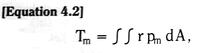
where the surface integral is taken over the entire armature bottom surface (the surface on the core side), pm is the magnetic pressure on the armature bottom surface, and r is the moment arm of the differential force pm dA. Since the armature is made of iron, the direction of magnetic flux flow through its exterior surface will be almost perfectly normal to the surface. In this case, the magnetic pressure [4.1] is given by 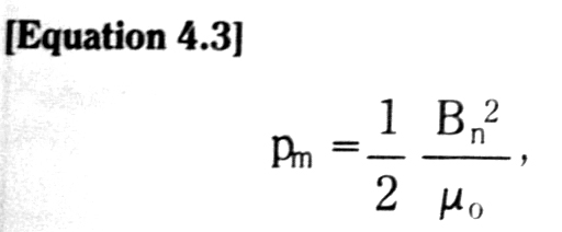
where Bn is the magnitude of the normally directed magnetic flux density vector at the armature surface, and µo is the magnetic permeability of free space (µo = 4π x 10-7 henries/meter). The magnetic permeability of a medium is a measure of the medium’s ability to conduct the flow of magnetic flux. Magnetic materials have relative permeabilities several thousand times that of free space. The total net magnetic force Fm on the armature, directed towards the core structure, is given by 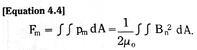
And the total magnetic flux фg, which flows through the bottom surface of the armature, and therefore, through the gap between the armature and the core, is given by 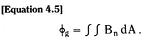We can now define an effective gap cross-sectional area Ag by equating the two force expressions
Such that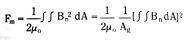
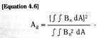
This effective gap cross-sectional area allows us to think of the armature as a free body, with a uniform magnetic pressure Fm/Ag, acting on a portion (Ag) of its lower surface. We can even define an effective moment arm rq for a point force Fm by equating
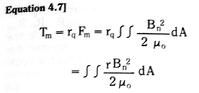
So that
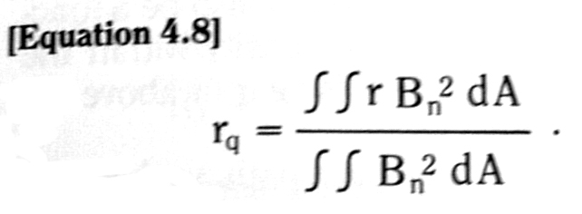
If the distribution of normal magnetic flux over the bottom surface of the armature does not change as the armature position or the driving coil current changes, the effective cross-sectional area of the gap Ag, and the effective armature moment arm rq, will both be constant (See Equations 4.6 and 4.8).The total magnetic torque on the armature is now simply given by 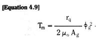
Equation 4.9 indicates that in order to increase the magnetic torque for any given armature structure, we need only increase the total gap flux. And, for a given input current, we need only to control the time development of the total gap flux, if we wish to control the time response of a magnetic breaker detection mechanism.
0 Comments [Click here to read/write comments](https://www.mechprod.com/blog-old/bid/301839/Magnetic-Force#comments-listing)
Tags: [Electromagnetic structure](https://www.mechprod.com/blog-old/topic/electromagnetic-structure), [Magnetic Torque](https://www.mechprod.com/blog-old/topic/magnetic-torque), [Armature-latch release mechanism](https://www.mechprod.com/blog-old/topic/armature-latch-release-mechanism)
[All posts](https://www.mechprod.com/blog-old/all)
### Follow us!
### Subscribe by Email
### Latest Posts
### Posts by Month
- [May 2012 (4)](https://www.mechprod.com/blog-old/archive/2012/05)
- [July 2012 (3)](https://www.mechprod.com/blog-old/archive/2012/07)
- [April 2013 (3)](https://www.mechprod.com/blog-old/archive/2013/04)
**Mechanical Products**
**Count on MP for your thermal circuit breaker needs**
Tel: 630.953.4100 | Fax: 630.953.4110 | Email: [helpme@mechprod.com](mailto:helpme@mechprod.com)
**www.mechprod.com**