Overcurrents and protective devices are not new subjects. Soon after Volta constructed his first electrochemical cell, or Faraday spun his first disk generator, someone else graciously supplied these inventors with their first short circuit loads. Patents on mechanical circuit-breaking devices go back to the late 1800’s and the concept of a fuse goes all the way back to the first undersized wire that connected a generator to a load.
In a practical sense, we can say that no advance in electrical science can proceed without a corresponding advance in protection science. An electric utility company would never connect a new generator, a new transformer, or a new electrical load to a circuit that cannot automatically open by means of a protective device. Similarly, a design engineer should never design a new electronic power supply that does not automatically protect its solid-state power components in case of a shorted output. Protection from overcurrent damage must be inherent to any new development in electrical apparatus. Anything less leaves the apparatus or circuit susceptible to damage or total destruction within a relatively short time.
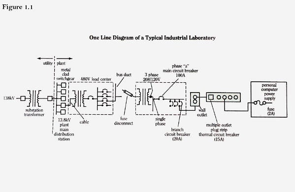

Examples of overcurrent protection devices are many: fuses, electromechanical circuit breakers, and solid state power switches. They are utilized in every conceivable electrical system where there is the possibility of overcurrent damage. As a simple example, consider the typical industrial laboratory electrical system shown in Figure 1.1. We show a one-line diagram of the radial distribution of electrical energy, starting from the utility distribution substation, going through the industrial plant, and ending in a small laboratory personal computer. The system is said to be radial since all branch circuits, including the utility branch circuits, radiate from central tie points. There is only a single feed line for each circuit. There are other network type distribution systems for utilities, where some feed lines are paralleled. But the radial system is the most common and the simplest to protect.
Overcurrent protection is seen to be a series connection of cascading current-interrupting devices. Starting from the load end, we have a dual-element or slow-blow fuse at the input of the power supply to the personal computer. This fuse will open the 120 volt circuit for any large fault within the computer. The large inrush current that occurs for a very short time when the computer is first turned on is masked by the slow element within the fuse. Very large fault currents are detected and cleared by the fast element within the fuse.
Protection against excess load at the plug strip, is provided by the thermal circuit breaker within the plug strip. The thermal circuit breaker depends on differential expansion of dissimilar metals, which forces the mechanical opening of electrical contacts.
The 120 volt single-phase branch circuit, within the laboratory which supplies the plug strip, has its own branch breaker in the laboratory’s main breaker box or panel board. This branch breaker is a combination thermal and magnetic or thermal-mag breaker. It has a bi-metallic element which, when heated by an overcurrent, will trip the device. It also has a magnetic-assist winding which, by a solenoid type effect, speeds the response under heavy fault currents.
All of the branch circuits on a given phase of the laboratory’s 3-phase system join within the main breaker box and pass through the main circuit breaker of that phase, which is also a thermal magnetic unit. This main breaker is purely for back up protection. If, for any reason, a branch circuit breaker fails to interrupt overcurrents on that particular phase within the laboratory wiring, the main breaker will open a short time after the branch breaker should have opened.
Back-up is an important function in overload protection. In a purely radial system, such as the laboratory system in Figure 1.1, we can easily see the cascade action in which each overcurrent protection device backs up the devices downstream from it. If the computer power supply fuse fails to function properly, then the plug strip thermal breaker will respond, after a certain coordination delay. If it should also fail, then the branch breaker should back them both up, again after a certain coordination delay. This coordination delay is needed by the back-up device to give the primary protection device – the device which is electrically closest to the overload or fault – a chance to respond first. The coordination delay is the principal means by which a back-up system is selective in its protection.
Selectivity is the property of a protection system by which only the minimum amount of system functions are disconnected in order to alleviate an overcurrent situation. A power delivery system which is selectively protected will be far more reliable than one which is not.
For example, in the laboratory system of Figure 1.1, a short within the computer power cord should be attended to only by the thermal breaker in the plug strip. All other loads on the branch circuit, as well as the remaining loads within the laboratory, should continue to be served. Even if the breaker within the plug strip fails to respond to the fault within the computer power cord, and the branch breaker in the main breaker box, is forced into interruptive action, only that particular branch circuit is de-energized. Loads on the other branch circuits within the laboratory still continue to be served. In order for a fault within the computer power cord to cause a total blackout within the laboratory, two series-connected breakers would have to fail simultaneously – the probability of which is extremely small.
The ability of a particular overcurrent protection device to interrupt a given level of overcurrent depends on the device sensitivity. In general, all overcurrent protection devices, no matter the type or principles of operation, respond faster when the levels of overcurrent are higher.
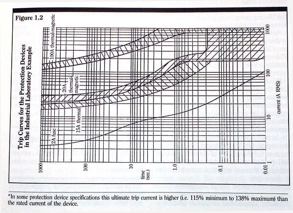
Coordination of overcurrent protection requires that application engineers have detailed knowledge of the total range of response for particular protection devices. This information is contained in the “trip time vs. current curves,” commonly referred to as the trip curves. A trip time-current curve displays the range of, and the times of response for, the currents for which the device will interrupt current flow at a given level of circuit voltage. For example, the time current curves for the protection devices in our laboratory example are shown superimposed in Figure 1.2.
The rated current for a device is the highest steady-state current level at which the device will not trip for a given ambient temperature. The steady-state trip current is referred to as the ultimate trip current. The ratings for the dual-element fuse in the computer power supply, the plug strip thermal breaker, the branch circuit thermal-magnetic breaker and the main circuit thermal-magnetic breaker are 2, 15, 20, and 100 amps, respectively. Note that, except for the fuse curve, each time-current curve is shown as a shaded area, representing the range of response for each device. Manufacturing tolerances and material property inconsistencies are responsible for these banded sets of responses. Trip time-current information for small fuses is usually represented in a single-value average melting time curve.
Even with a finite width to the time-current curves, we can easily see the selectivity/coordination between the different protection devices. For any given steady-state level of overcurrent, we read up the trip time-current plot, at that level of current, to determine the order of response.
Consider the following three examples for the laboratory wiring, plug strip, and computer system.
Example 1: Component failure within the computer power supply: Assume that a power component within the computer power supply has failed – say two legs of the bridge power rectifier – and that the resulting fault current within the supply, limited by a surge resister, is 70 amps.
We see from the fuse trip curve that it should clear this level of current in approximately 20 milliseconds. If the fuse fails to interrupt the current – or worse, if the fuse has been replaced with a permanent short circuit by a gambling repairperson – the thermal breaker in the plug strip should open the circuit within 0.6 to 3.5 seconds. The branch thermal-magnetic breaker will open the entire branch circuit within 3.5 to 7.0 seconds, should the plug strip thermal breaker also fail to respond. Note that no back-up is provided for this particular fault after the branch circuit breaker. The main laboratory 100 amp thermal-magnetic unit would respond only if the other loads within the entire laboratory totaled greater than 30 amps at the time of the 70 amp power supply fault.
Example 2: Plug strip overload: Assume that the computer operator has spilled a drink, and to dry up the mess plugs two 1500 watt hair dryers into the plug strip. The operator then flips them both on simultaneously, drawing a total plug strip load current of approximately 30 amps.
From the thermal breaker trip curve, we see that the plug strip unit should clear this overload within 5 to 30 seconds. Note the similarity between the trip curves of the plug strip thermal unit and the branch circuit thermal-magnetic unit in the region of 100 amps and below. This is because, for these levels of currents, the thermal portion of the detection mechanism within the thermal-magnetic branch breaker is dominant.
Example 3: Short circuit within the computer power cord: Assume a frayed line cord finally shorts during some mechanical movement. Assume also that there is enough resistance within the circuit, plug strip, and line cord system to limit the resulting fault current to 300 amps. This level of current is 2000% (20 times) of the rated current of the plug strip thermal breaker, and is beyond the normal range of published trip time specifications for thermal breakers (100% to 1000% of rated current). Thus the exact trip time range of the thermal unit is indeterminate.
At high levels of fault current, greater than 150 amps in this case, we can see the inherent speed advantage of magnetic detection of overcurrents. This is evidenced by the fact that the response curve for the thermal-magnetic branch circuit breaker knees downward sharply at current levels between 150 and 200 amps. At these and higher currents, the magnetic detection mechanism within the thermal-magnetic unit is dominant. The response curve for the unit crosses over the plug strip thermal breaker response curve (assuming that it extends past its 1000% limit), and coordination between the two interrupters is lost. The range of response for the thermal-magnetic breaker at 300 amps is 8 to 185 milliseconds. Should both the plug strip breaker and the branch circuit breaker fail to operate, the main laboratory breaker should clear the fault within 11 to 40 seconds.